|
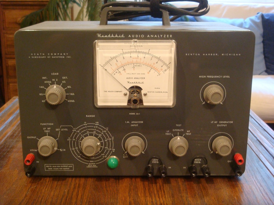
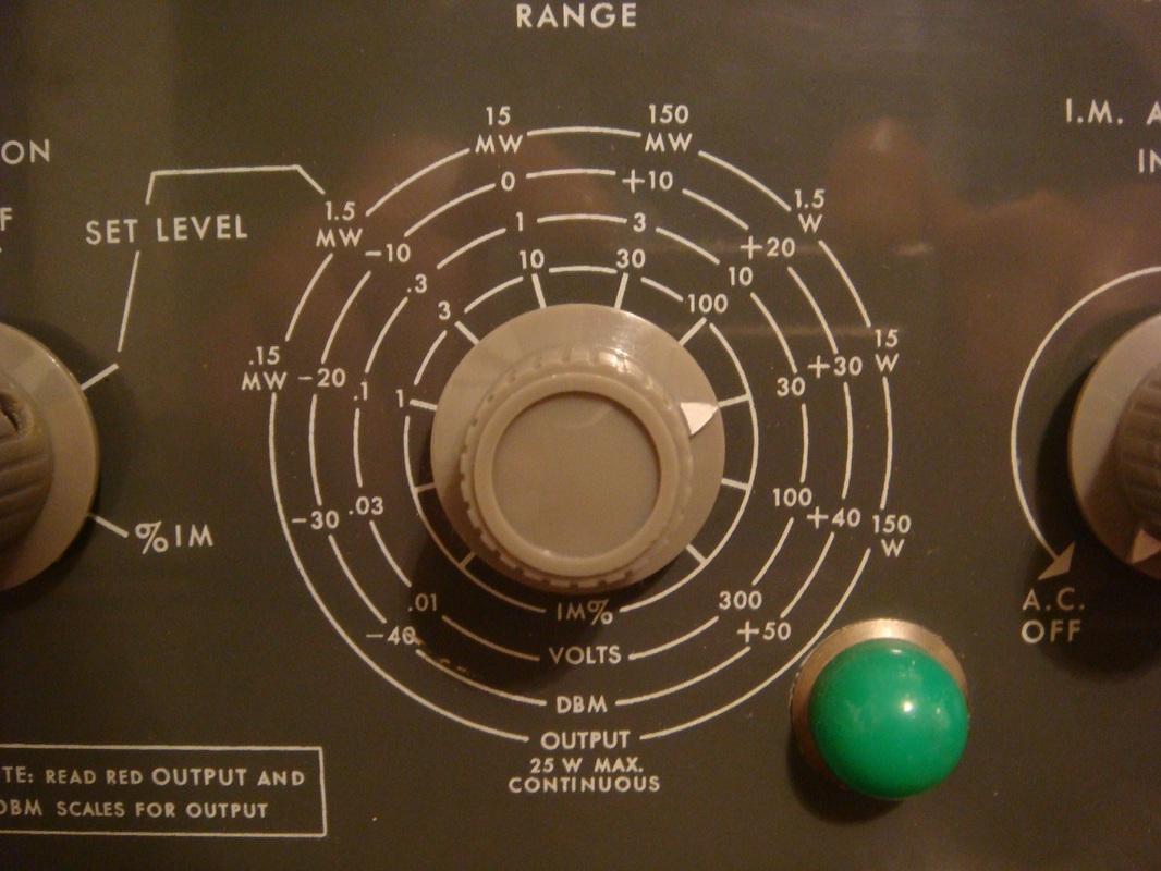
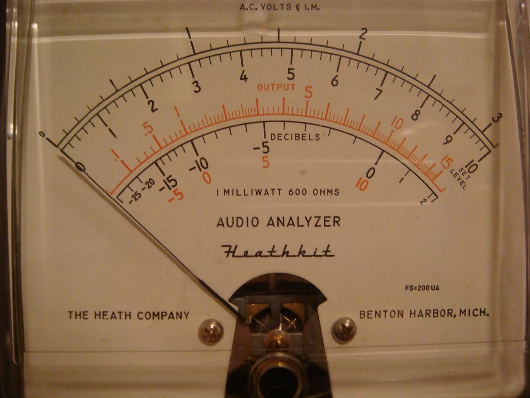
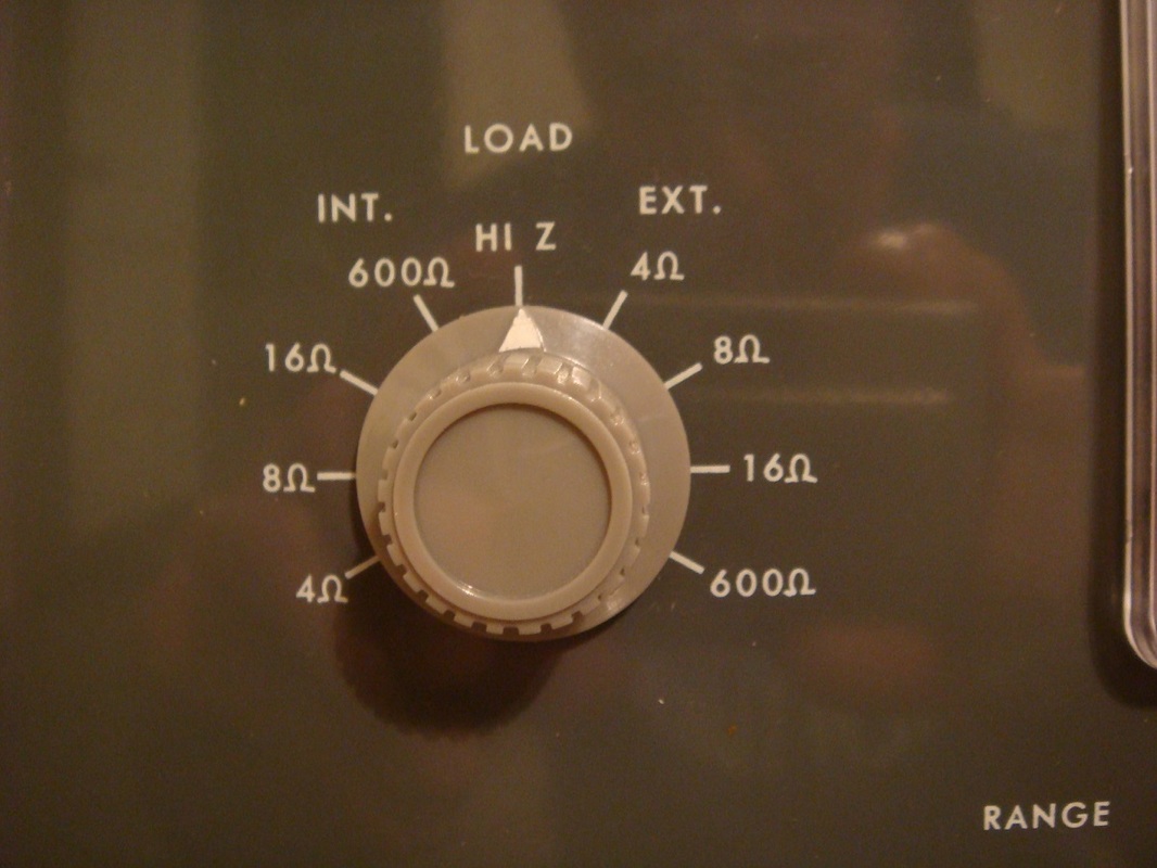
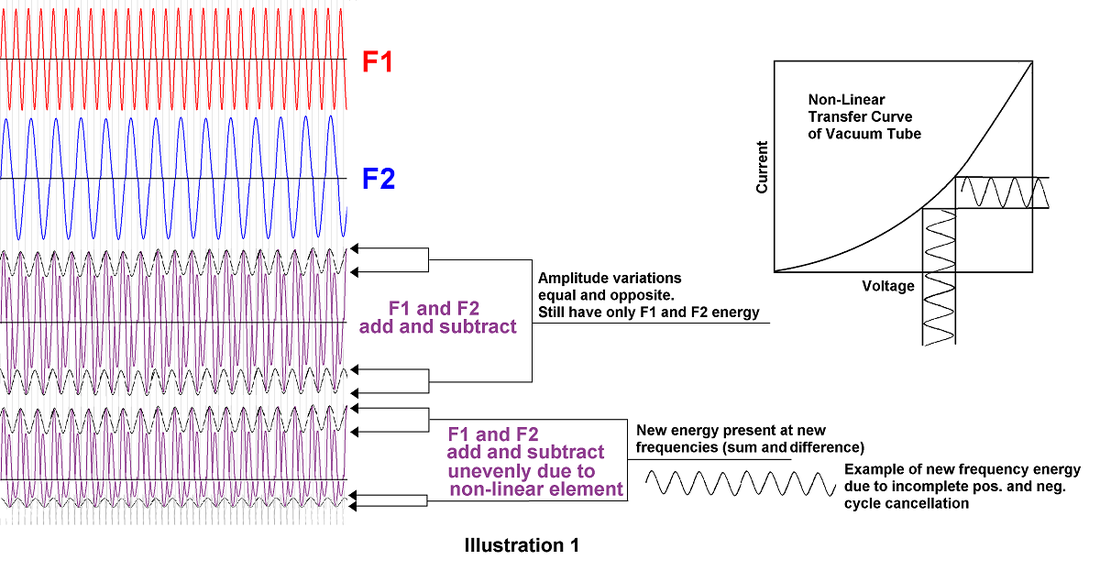
Disclaimer The content of this website and blog has been created and posted here solely for the purposes of reading interest by Rob's Radio-Active, LLC. The content is the thoughts of the author and is not intended to be an authoritative guide. There may be errors and omissions. Electronic and electrical devices pose a potential hazard to life and property if improperly handled, used, or serviced. The author cannot possibly think of, and warn of, all the ways one can get into trouble with electricity, and recommends one learn all of the technical and safety aspects of electrical/electronics before attempting to work with or use any of it. There are hazardous voltages and currents involved in almost all electrical and electronic equipment—especially vacuum tube devices or anything that plugs into mains current for operation. Furthermore, vintage equipment was never designed or built to be up the safety standards of modern times. Most of the articles I post (or will post) here are intended, hopefully, to help restorers of vintage radios or test equipment troubleshoot or fix up their acquisitions. I hope the article, Meter Workarounds and Accessories, for example, will show a few ways to use common meters to measure electrical quantities in ways the reader may not know about that expands the capability of their meter(s)—especially someone just starting out that doesn't yet own a lot of specialized test equipment. This article may not be directly helpful in the same way, but what can I say? I found a good AA-1. I bought it. I restored it. I use it. I hope you find it interesting. The AA-1 is a three-in-one test unit containing a sensitive AC (only) vacuum tube voltmeter, an audio power meter with built-in dummy loads to substitute for the speakers, and an intermodulation distortion meter. All three functions are very useful on vintage audio amplifiers and tube guitar amplifiers, too; it is indeed convenient to have them available in one unit rather than a bench full of separate testing devices. Of course, you will still need at least a general purpose voltmeter/ohmmeter for fully testing or troubleshooting your audio equipment. Though I wouldn't drag this unit out to do more than cursory checks on modern, high powered, high end audio with harmonic distortion in the tiny fraction of a percent— it is not sensitive enough for that—it serves me well for testing old tube equipment or "average" amplifiers. The AC VTVM ranges from 10mVRMS to 300VRMS and -65dBm to +52dBm for full scale meter deflection and has a flat response across the entire audio range and then some. This is sensitive enough for typical phono outputs or the signal voltages produced by electric guitar pickups. When set to measure audio power, the output of the amplifier is connected to the AA-1's internal load resistors which can be selected at 4Ω, 8Ω, 16Ω, or 600Ω. The 600Ω is used for pre-amps designed to feed a 600Ω impedance line to a power amplifier. The load resistors were stated to handle 25 watts continuous, or 50 watts for a quick, temporary power test, though the meter maximum is 150 watts, presumably for external loads. I had to replace most of mine with 20 watt, non-inductive power resistors as all the originals except the 600Ω were open, so now the 8Ω will only handle 20 watts, continuous, but the 4Ω and 16Ω loads were made up of two, 20 watt resistors each and should be able to handle about 40 watts. The power scale is the red, non-linear scale on the VTVM meter face labeled "output." The AC VTVM setting for audio signal voltage in high impedance circuits is the "high Z" setting on the selector switch below. This selects the AA-1's 1 megohm input for measuring signal gain in amplifier stages and things like that. The intermodulation distortion measurement function is read on the same scales as the voltage, but interpreted as percentage of the range scale setting's maximum rather than voltage. For example, a meter indication of 4, when the IM selector is in the 10% full scale position, simply indicates 4% intermodulation distortion. So what is intermodulation distortion and how does the analyzer measure it? I am not qualified to write a lengthy and detailed survey of audio distortion, but I will try to cover the basics as I understand them. Illustration 1 below is highly simplified and may not be strictly correct, but I think it gives a general feeling to what happens when two or more AC waveforms come together. When F1 and F2 signal voltages are combined across a "linear" element like a resistor—that is, one in which the current flow is a straight function of the voltage across it—they periodically add and subtract. At times where both waveforms are positive at the same time, their voltages add together. When their polarities are opposite, they cancel each other out to some extent, and we end up with a total voltage waveform across the resistor that looks something like the third waveform from the top. We still only have F1 energy and F2 energy together across the resistor. There are positive peaks and negative peaks of the total voltage but the they are equal and opposite. In a sense, then, they cancel the total energy of the amplitude variations that were created when F1 and F2 came together. If, however, F1 and F2 are applied across or through an element that has a non-linear characteristic to its voltage vs. current relationship, such as a diode, transistor, or vacuum tube, there will tend to be more current passed through, or "gain" in the case of an amplifier at the positive or negative peaks of the amplitude variation caused by the two waveforms adding and subtracting. This results in an incomplete cancellation of the total energy present at the sum and difference frequencies of the two waveforms. Therefore, in addition to the two original frequencies, we have new energy there at the sum and difference frequencies. If F1 were 1kHz and F2 were 1.5kHz, for example, Now there would be present 1kHz, 1.5kHz, 500Hz, and 2500Hz. So we just added some new waveforms or "sidebands" to the circuit. An example of just one new energy waveform is shown in the illustration. Alright, so that is my personal, basic and simplified concept of the non-linear effect on two or more frequencies known as "mixing" or generating "beat frequencies." So what? Well, since it's a fact that mixing in a non-linear element results in new frequency energies being generated, the tendency is for more energy to be generated in a less linear circuit than in a more linear circuit, all other things being equal. What an intermodulation distortion test does, in effect, is run two non-harmonically related frequencies (not an even multiple of each other)and of a known relative voltage level, through an amplifier under test and looks at how much new waveform energy is produced. This all can be calibrated to give a reading of this type of distortion. Another way to describe what is happening to the input frequencies is that the lower frequency is actually modulating the higher one—because generating these new sidebands is what happens whenever any waveform is amplitude modulated. It's the same thing. The more non-linear the amplifier, the more the distortion, the more amplitude modulation occurs, the more new sideband energy becomes present in the mixed signal. If we filter out and measure the sum or difference frequency energy (voltage, really) with known inputs we can read the percentage of intermodulation distortion which will give us a relative value of the ability of the amplifier to reproduce a complex audio input signal without changing it by adding or subtracting anything. A linear and high fidelity amplifier will cause two input signals to modulate very little, and there will be ideally be practically only the original tones present. By the way, the common measurement nowadays is "total harmonic distortion" rather than IM distortion, but they go hand in hand. You cannot have one without the other. After all, a sideband generated by modulation is a harmonic of the original frequency. The amplifier added something that wasn't there before due to non-linearity, and it changed the sound. They are related therefore, but measure differently. This unit measures only IM distortion, but can give a good idea of the fidelity capability of an amplifier. Adjusting an amplifier for minimum IM will bring down THD and increase fidelity. So how does the AA-1 do this? Simple in principle: The AA-1 has a 60Hz voltage source and an internal audio oscillator that runs at about 6kHz to 7kHz. The relative level of these two signals is adjusted, using the AA-1 meter, to a four to one voltage ratio. In other words, the 60Hz level is set to four times the voltage of the high frequency oscillator voltage. Then the two are set to an overall level to make the meter read "set level" to calibrate the meter. The two signals are then applied to the amplifier under test and any non-linearity in the amplifier will cause the low frequency to modulate the high frequency, creating sidebands. This modulated energy is picked off the output signal by the AA-1's bandpass filter system, amplified, and demodulated by a rectifier. The level of the new signal created by intermodulation is a filtered DC that drives the previously calibrated meter to read percentage of IM distortion. How much IMD is too much? Well that depends. On a guitar amplifier, the amp is part of the instrument and you would normally want at least a certain amount of the proper kind of distortion. I will leave that discussion to the wide world of musical instrument amplification and all the opinions and tastes therein. Other than to find out which stages are contributing the most to this kind of distortion, I do not use the IMD function of the AA-1 on instrument amplifiers. For Hi-Fi amplifiers, lower is better, of course. Opinions and even listener studies vary widely about how much THD or IMD can be perceived, but even that depends on the type of music being played. I will leave this to the reader to determine, as this is just a little article about a vintage piece of test equipment, after all.
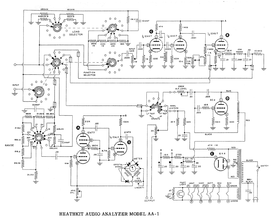
There are a lot of ways to test your amplifiers with oscilloscopes and other test equipment, but I love the old stuff and find it immensely interesting how the old time engineers developed these kinds of instruments so a kit-builder and home hobbyist, or a technician on a budget could afford a specialized tester that may have fallen short of laboratory grade accuracy and capability, but actually worked pretty well for servicing factory made electronics or testing one's own designs. Thanks for reading! © 2016 Rob's Radio-Active, LLC All Rights Reserved Schematic Below
0 Comments
|

 RSS Feed
