|
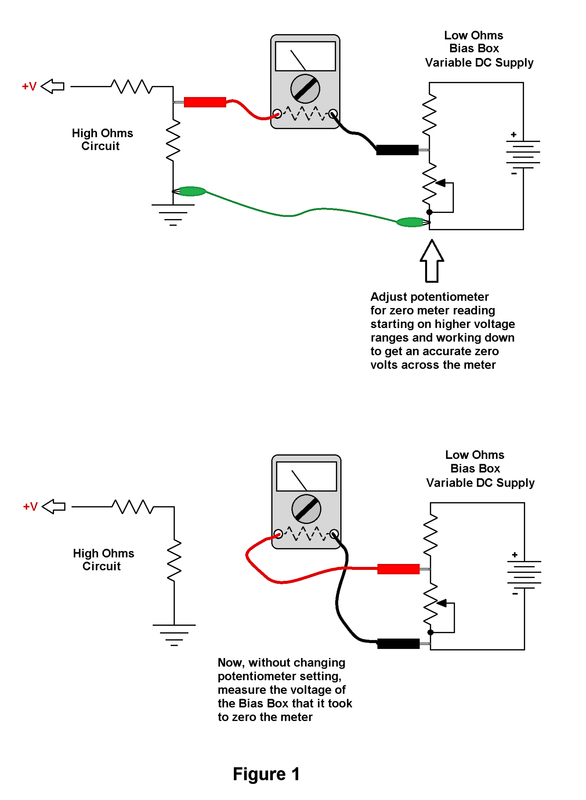
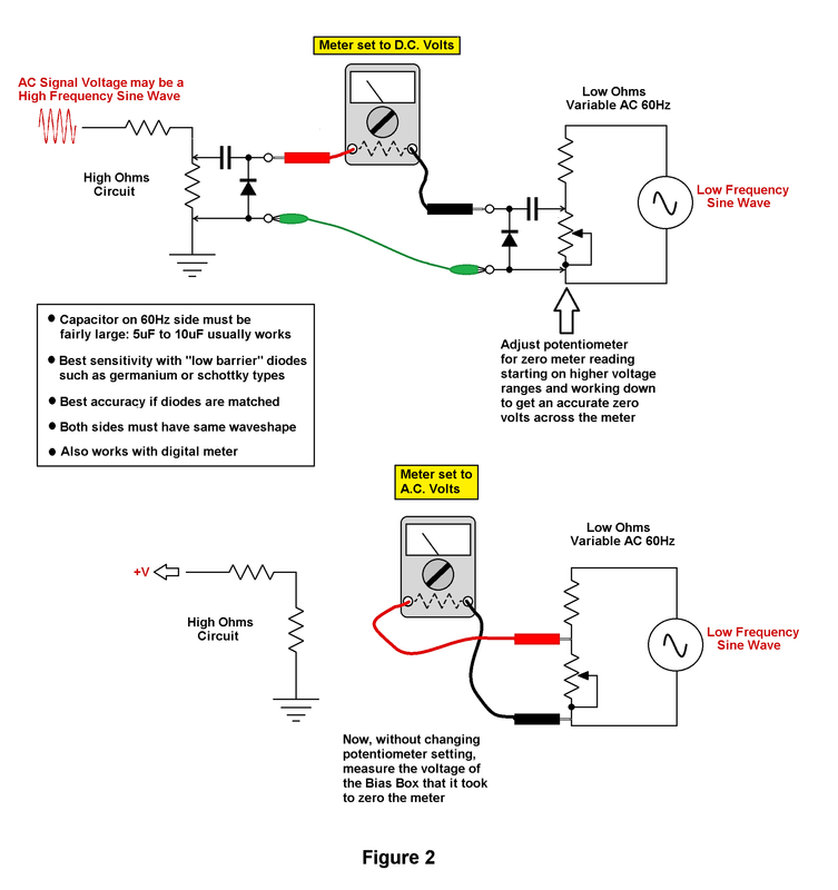
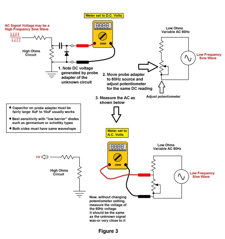
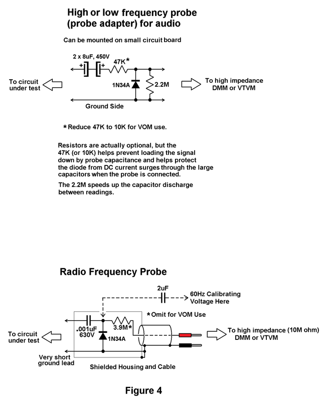
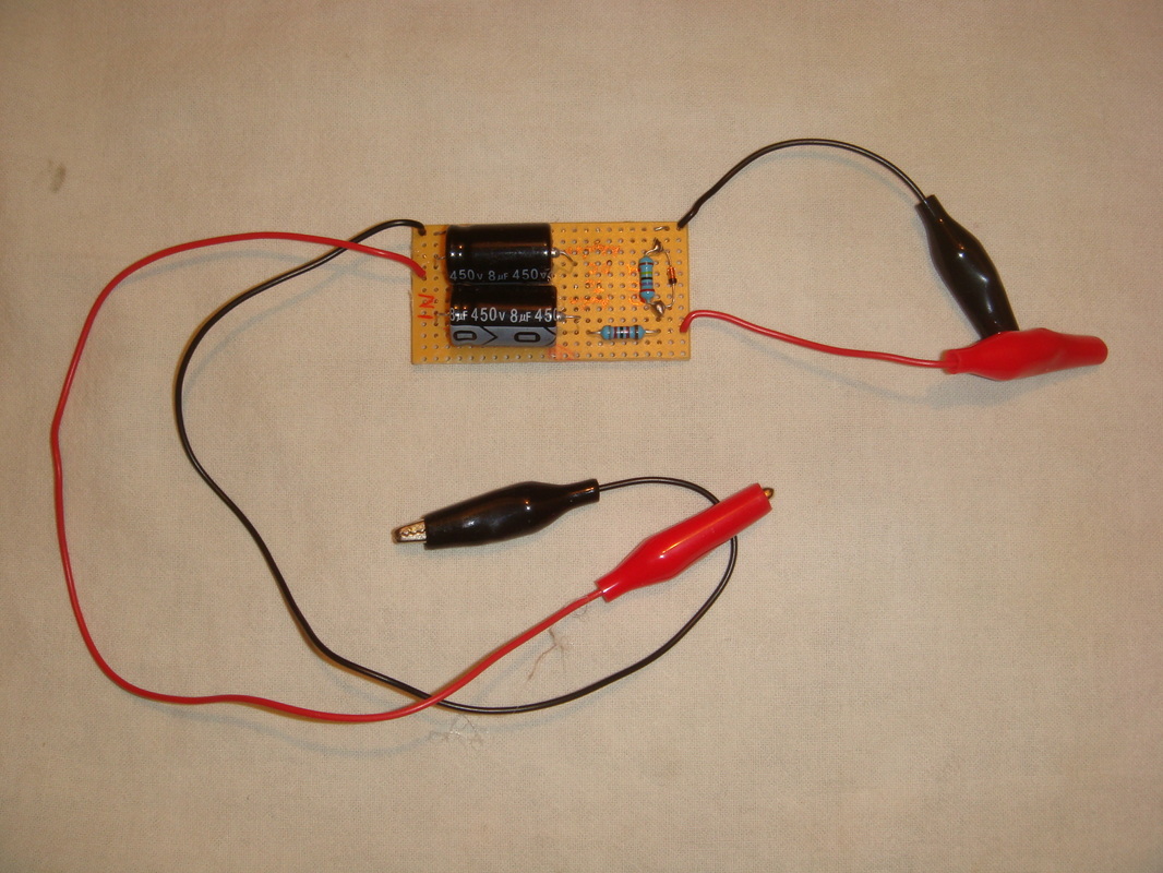
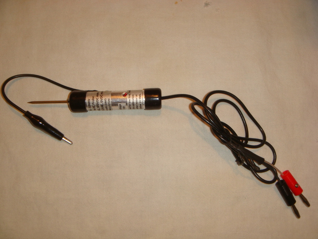
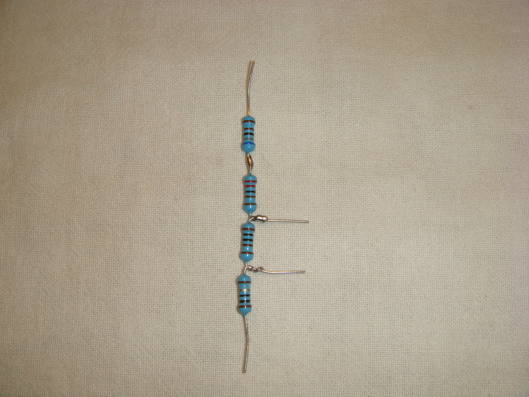
Disclaimer The content of this website and blog has been created and posted here solely for the purposes of reading interest by Rob's Radio-Active, LLC. The content is the thoughts of the author and is not intended to be an authoritative guide. There may be errors and omissions. Electronic and electrical devices pose a potential hazard to life and property if improperly handled, used, or serviced. The author cannot possibly think of, and warn of, all the ways one can get into trouble with electricity, and recommends one learn all of the technical and safety aspects of electrical/electronics before attempting to work with or use any of it. There are hazardous voltages and currents involved in almost all electrical and electronic equipment—especially vacuum tube devices or anything that plugs into mains current for operation. Furthermore, vintage equipment was never designed or built to be up the safety standards of modern times. Workarounds In the Vacuum Tube Voltmeter blog, I mentioned that there are various "workarounds" for extending the usefulness of your VOM or DMM. If you have ever read "101 Ways to Use Your VOM or VTVM" by Robert Middleton, you will see that there are many ways to build or buy simple probe accessories and use various meter hookups to use an ordinary multimeter to measure everything from signal distortion to radio frequency voltages. A couple that I find most useful are the being able to accurately measure high impedance circuit voltages with a relatively low impedance VOM, and being able to use you DMM (or sometimes a VOM) to measure a wide frequency range—well outside of the frequency response of the meter. The first method in the illustration below (Figure 1) shows how to use your VOM as a "potentiometric" voltmeter that draws no current (practically speaking) from a high impedance circuit, to avoid the possibility of loading down the voltage and getting an inaccurate reading. The principle is to use the meter as a null indicator between the circuit under test and a relatively low internal impedance DC supply voltage, often called a "bias box." By working down from the high voltage ranges to the low, and adjusting the bias box potentiometer to zero the meter, what we have done is set the bias box output to the same voltage as the unknown voltage. The meter reading zero indicated the voltages are balance and that no current is being drawn by the VOM. Then, without changing the bias box setting in any way, we can measure its voltage—which will be the same as the unknown voltage. The VOM will not, however, load down the bias box due to the box's relatively low impedance so we can rely on that voltage measured by the low impedance VOM, whereas we could not rely on the high impedance circuit voltage if directly measured by the VOM. Figure 2 shows how we can do exactly the same thing with measurement of an AC voltage or signal—but we need to build two rectifying probe adapters to convert the AC voltage or signal into DC. We need two, because we need to zero the meter now with an AC bias box. The AC of both the signal and the bias box will be converted to DC, approximately equal to the peak value of AC wave, to balance the meter. 60Hz stepped down by a transformer and regulated with a voltage divider works fine, as long as it is relatively low impedance compared to the VOM as before. Why can't we just use the DC bias box on the right hand side or the illustration? Because we need to account for diode voltage drop, which varies with its forward current, and its voltage drop will only match when AC of the same waveform is applied to each probe adapter. Strictly speaking, with matched diodes—but most are close enough if of the same type. Do not forget to switch the meter to AC volts to measure the 60Hz AC bias box. The other most important workaround involves the reading of AC frequencies well outside of the bandwidth of a DMM. Most DMMs are rated for up to perhaps 500Hz, and are really only accurate to 1 or 2kHz. (A VOM can be used here, but a DMM works better.) For this we only need one AC to DC probe adapter. The idea is the same as before, in that we can get a DC voltage from a circuit under test at a wide range of frequencies, and then, since we know that the voltage level will only be an approximate proportion of the input signal, we can then compare it to a variable AC voltage that we can measure directly and accurately with the meter. As figure 3 shows, we get a DC number from the circuit under test through the AC to DC probe adapter and then set the AC bias box to make the meter read the same DC. We can then switch the meter to AC volts, and read the 60Hz bias box voltage. The signal and the 60Hz should be very close to the same. I have used this method to good effect to press a DMM into service for measuring audio voltages in amplifiers from 20Hz to more than 20kHz. (Figure 3) A trick for measuring audio amplifier gain at the first stage with a very small input signal is to feed a signal of 1 volt, RMS (for this example) across a resistive attenuator made up of a 10K resistor in series with a 10 ohm resistor. The 1 volt is easily measured and set accurately by the previous methods, and if the amplifier input is tapped across the 10 ohm resistor, we know we are feeding 1 mV to the amplifier. We can then use these methods above to measure the output of the amplifier stage. If we get 100mV, for this example, we know the voltage gain is 100. This, of course, can be mathematically converted to dB if we wish. Normally I would use a scope and/or a sensitive AC millivoltmeter to do this, but it is good to know that an ordinary DMM or VOM can be adapted by cheap, homebrew accessories and the correct methods to make them do much more than they could do if we only used direct measurements.The above method also works well at radio frequencies, too, as long as the probe adapter is well designed for those higher frequencies with a small input capacitor, short leads, and a shielded cable and probe handle. (See Figure 4) Since the small capacitor will offer lower self inductance and work much better at RF than a large capacitor, but will not pass the 60Hz calibration voltage of the AC bias box very well, it must be bypassed with a larger capacitor for reading the bias box voltage. You cannot just skip the capacitor, either, and feed 60Hz into the RF probe. The capacitors in all of these little helpers are essential to their operation. They charge to the approximate peak voltage of the AC and feed that DC to the meter. Without them, and just a diode, the meter will get a pulsating DC voltage and only read the average of that wave. Also, since there would be no peak DC voltage on the probe side of the circuit to balance the peak voltage pulses on the test side, it would tend draw excessive current from the circuit under test and would excessively load down that circuit. I usually use germanium diodes I get from eBay, but schottky diodes are almost as sensitive. Using these with a DMM that can read millivolts accurately, I can measure all of these frequencies down to several millivolts. An ordinary silicon fast switching diode like a 1N4148 will work fine, but will not get down to as low of a voltage sensitivity. A trick for measuring audio amplifier gain at the first stage with a very small input signal is to feed a signal of 1 volt, RMS (for this example) across a resistive attenuator made up of a 10K resistor in series with a 10 ohm resistor. The 1 volt is easily measured and set accurately by the previous methods, and if the amplifier input is tapped across the 10 ohm resistor, we know we are feeding 1 mV to the amplifier. We can then use these methods above to measure the output of the amplifier stage. If we get 100mV, for this example, we know the voltage gain is 100. This, of course, can be mathematically converted to dB if we wish. Normally I would use a scope and/or a sensitive AC millivoltmeter to do this, but it is good to know that an ordinary DMM or VOM can be adapted by cheap, homebrew accessories and the correct methods to make them do much more than they could do if we only used direct measurements. Audio probe and RF Probe: Note the little red wire tip coming out the side of the RF probe is where I attach a non-polarized 10uF capacitor to feed in a 60Hz calibration (comparison voltage) as described above. My 1000:1 resistive attenuator—simple. Measuring as above, I can use an ordinary DMM to know I am feeding, say, 1 volt to the attenuator, and know that I am tapping exactly 1 mV signal to an amplifier (which is too small to measure by these methods—hence the attenuator. The output of an amp stage then will usually have enough voltage to measure with my DMM and AC to DC probe adapter. This allows gain calculation when dealing with very small input signals. That's all for now. I hope you found it interesting!
© 2016 Rob's Radio-Active, LLC All Rights Reserved
5 Comments
|
 RSS Feed
