|
Disclaimer The content of this website and blog has been created and posted here solely for the purposes of reading interest by Rob's Radio-Active, LLC. The content is the thoughts of the author and is not intended to be an authoritative guide. There may be errors and omissions. Electronic and electrical devices pose a potential hazard to life and property if improperly handled, used, or serviced. The author cannot possibly think of, and warn of, all the ways one can get into trouble with electricity, and recommends one learn all of the technical and safety aspects of electrical/electronics before attempting to work with or use any of it. There are hazardous voltages and currents involved in almost all electrical and electronic equipment—especially vacuum tube devices or anything that plugs into mains current for operation. Furthermore, vintage equipment was never designed or built to be up the safety standards of modern times. This article is about the world's greatest voltmeter—the oscilloscope. You can do about anything with a typical modern era 2 channel (that is, not necessarily a 1950s or '60s tube operated type) scope that you can do with any other voltmeter. You can even measure the voltage of your 9V battery; not that you would, unless your regular meter was broken. You can even measure resistance and current in a circuit with a little bit of clever circuit adaptation and calculating—just like a regular, dedicated voltmeter could do. The real usefulness of the scope, of course, is that is allows you to see the waveform as well as make calibrated measurements of it. It can show parasitic oscillation or distortion that a plain voltmeter will not. These things make a scope useful for signal tracing in a malfunctioning electronic device or finding performance issues such as signal "clipping" in a circuit–perhaps an audio amplifier–in the construction and testing phase. Personally, I can troubleshoot broken vintage radios all week without a scope, but I always use one when testing a guitar or audio amp that I am building. There are plenty of basic oscilloscope tutorials out there in web-land, and this article will be brief on its review of basic operation, but I want to cover a few of the less obvious features and pitfalls of use. Also, here we will focus on a typical type analog scope that many, many hobbyists have. Digital Storage Oscilloscopes (DSO) all have similar features and capabilities (and more) but the settings are usually done by scrolling through menus. They are all a bit different and you really have to read the manual and play with it some to find out exactly how to set them up. Still, if you can operate an analog scope from the 1980s or '90s, you understand the principles and can operate a DSO with little trouble. They also save on calculating things like signal frequency and RMS voltage because they can calculate all this automatically and display that information right on the screen. The very basic principle of oscilloscope function is that a voltage applied to the input is amplified and sent to move an illuminated spot on the screen. A positive voltage causes the spot to move upward and a negative voltage causes it to move downward. The direction of travel of the second input channel on a two channel unit can also be inverted with a switch on the front panel. The amplifiers are calibrated to move the spot a set amount for a given voltage, and the input volts per division selector can scale this amount in set, calibrated amounts. Therefore, a voltage to an input channel can be read, quantitatively, on the divisional marking on the screen–taking into account the scale setting of the volts per division dial. At the same time, a horizontal sweep of the spot is caused by a sawtooth shaped voltage generated within the scope. The horizontal sweep is calibrated in time in seconds (or milliseconds or microseconds) per division as set by the time per division dial. The spot sweeps smoothly from left to right at a steady pace. When it reaches the right hand side limit, it is "blanked out" or turned off briefly by the scope and returns very quickly to the left hand side to start over again. This causes the spot, which has a certain visual persistence on the screen, to trace out the waveform of any inputted AC signal–that is, a graphical representation of change in voltage relative to time. To prevent the waveform on the screen from jumping randomly around and becoming a blur, the scope also has a triggering function which starts the horizontal sweep at exactly the same time in the voltage of the inputted signal each time. This is also user adjustable and external triggering signals may be selected. The sweep, therefore, traces and retraces the same recurring waveform over itself on the screen to make it readable. Not so bad, huh? DSOs do all this with digital electronics and usually use a color, LCD screen instead of a cathode ray tube, but the result is basically the same. There are times when the user does not need to see a calibrated voltage displayed on one or both channels–in other words, doesn't care what the exact voltage is at the moment, but needs to easily see if the two channel waveforms match each other or vary in magnitude or shape. For this, most scopes have "uncal" settings where the height of the waveform can be changed at will to no particular value. This allows overlaying on channel's waveform with the other to compare them at the same magnitude. Usually an LED lights up to reminds the user that the magnitude displayed does not correspond to a particular voltage. When that little knob is turned all the way (usually clockwise) until it clicks in, the LED goes out and the scope is returned to its calibrated setting. Referring to figure 1, below, and more or less from top to bottom, the common controls are shown by the numbered arrows. Different oscilloscopes will vary:
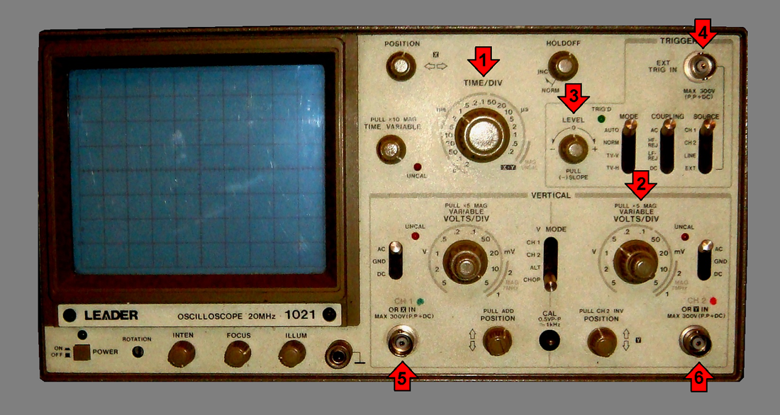 Above: Controls figure 1. Referring to Figure 2 below, some of the more esoteric controls are described:
A word about bandwidth and voltage limitations. This scope shown, as is typical, has a 300 volt input limit that is not to be exceeded. This limit includes the maximum peak level of any DC riding on top of it, so bear that in mind. The probes themselves normally have a x1 and x10 switch on them that when set to x10 will allow a higher voltage to be applied, as long as the probe voltage rating is not exceeded. The x10 increases the input impedance to ten times the x1 setting. This vastly reduces the effective shunt capacitance of the probe cable and allows accurate readings above a few megahertz. It will reduce the voltage the scope "sees" to one tenth, so the indication on the volts per division selector for that channel needs to be multiplied by 10. In other words, if the selector is set to 5mV per division it will really be showing 50mV per division with its probe set to x10. The bandwidth of a scope–in this example 20MHz–is the frequency limit of which the scope's response drops to -3dB, or about 0.707 times the actual input voltage. In practice, most scopes' responses are really pretty flat up to the limit, but bear in mind that it may drop by as much as this at the bandwidth limit. This doesn't mean the scope will not show a waveform at higher frequency, but the voltage inputted will be higher than the scope is indicating. 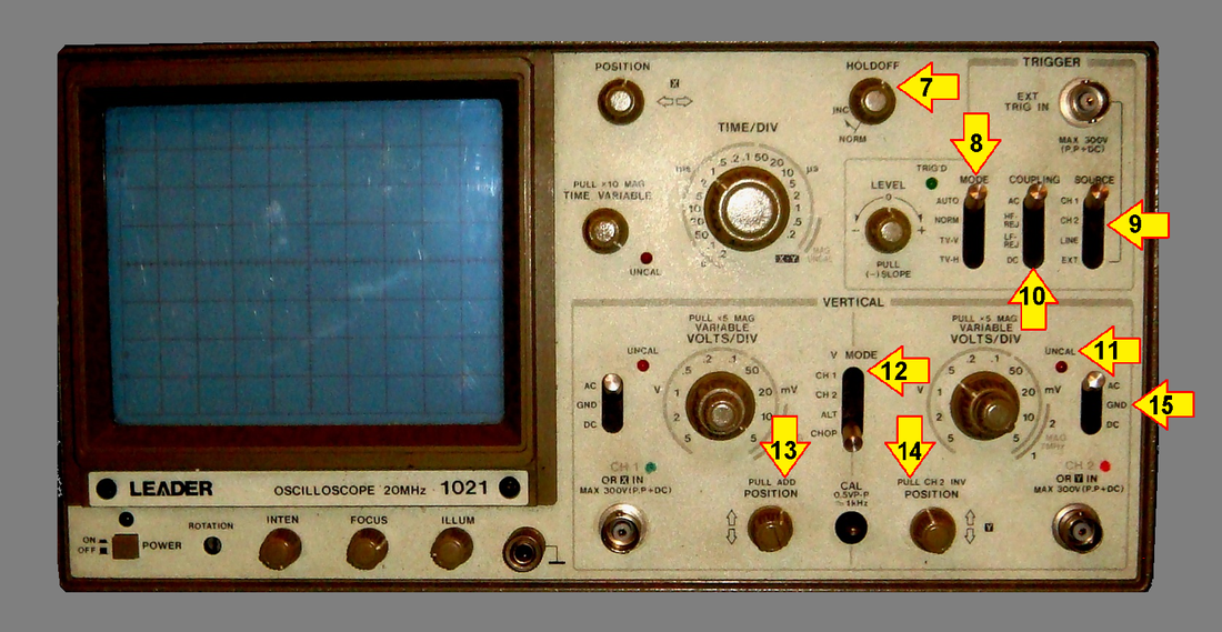 Above: Controls Figure 2. Reading an oscilloscope is pretty straightforward if you understand the controls above and know your basic electricity/electronics. In the example illustration below, a brief overview (or review) is shown to perhaps help clarify the matter. It should be fairly self-explanatory, I hope. I will only add a couple of hints: For frequency calculation, it is more accurate to set the time/division so that several complete cycles appear on screen, and then count as many full cycles there are and how many horizontal screen divisions those several cycles use rather than just counting divisions for one complete waveform cycle as shown in the illustration. For the most accurate voltage calculation, set the oscilloscope's volts/division so that the waveform takes up as much of the vertical screen space as possible without any of it going off screen and count the vertical divisions. Lastly, don't forget to have the scope in its calibrated (not the "uncal") setting and mind whether the probe is set to x1 or x10. 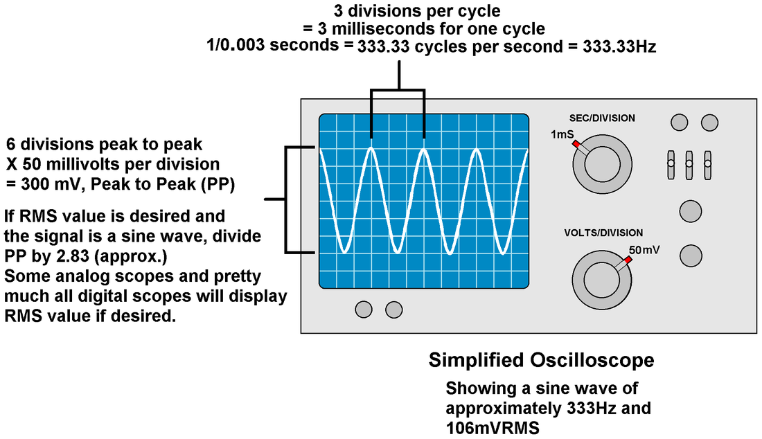 Above: Scope reading simplified. Next I would like to point out a few of the, perhaps, less obvious factors of proper oscilloscope operation. Most oscilloscopes plug into a wall receptacle and are grounded. That is to say that the metal enclosure and exposed fittings are connected directly to the building's power system earth ground. This includes the BNC type connectors' outer sleeves and the ground return clip on the probe handles. The earth ground in the building is connected to the "neutral" or (properly) grounded conductor in the main electrical panel–usually the white wire in the electrical box. This earth ground is also tied to the building's grounding rod or other conductor buried in the earth. The purpose of this is that is a short circuit to the metal casing occurs, for example, instead of the metal case being live at mains voltage with respect to the ground, which would make shock or electrocution a possibility, the current is supposed to rush to ground and blow a fuse or trip the circuit breaker to kill the power. The end result is that anytime you connect a probe tip and the ground return clip to measure a voltage, you are connecting whatever the clip is hooked to, to earth ground. This is usually not a problem, but in working on a circuit with a "hot" chassis (which you should never do without an isolation transformer anyway) there will be "fireworks." Another issue arises when you need to make a measurement of voltage between two points in a circuit that are both at some voltage above earth ground. This can also result in a nasty short–and you should never "lift" the oscilloscope's ground by plugging it into a non-grounding adapter or removing the grounding prong from its cord. This would remove the short to earth ground, but would leave the entire oscilloscope at a potentially lethal voltage. Sometimes, too, such as looking at the waveforms at different points coming from a bridge rectifier, connecting the two probes with their ground return clips in two different places will short circuit whatever component is between the ground clips. This is easy to see if you remember that the ground return clips going to the two input channels are not only earth grounded, but also connected to each other. Hopefully the illustrations below will help clarify these problems and their possible solutions. 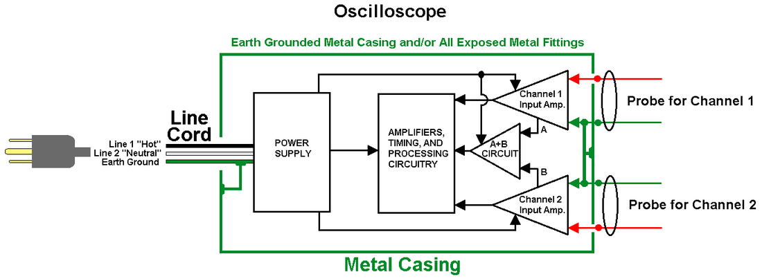 Above: The grounding system. 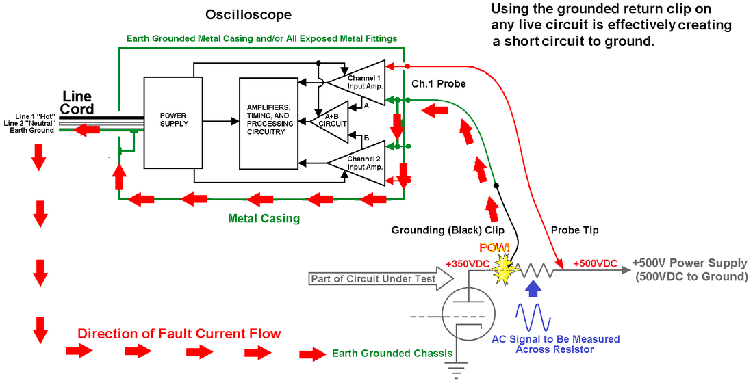 Above: Fault current. 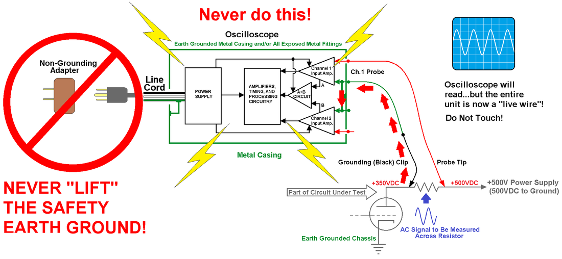 Above: "Lifting" a ground is dangerous in the extreme. 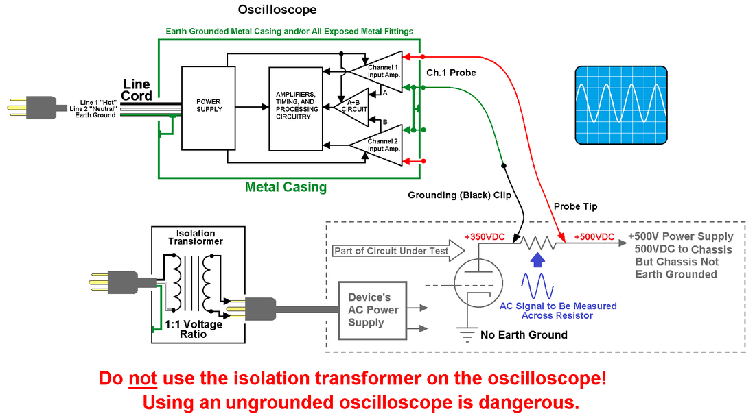 Above: Using an isolation transformer. 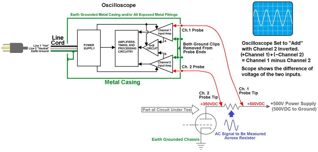 Above: Using the "A-B" method with both channels and no ground return clips. One more thing: don't forget that an oscilloscope can be pressed into service (like any other voltmeter) to measure current or even resistance–with a little temporary modification to the circuit being tested, and a little calculation with your handy pocket calculator. For example, placing a precision one ohm resistor in series with a circuit drawing current, and using the "A-B" method above, the voltage across the resistor can be observed and the current through it calculated. Say, for example, you read 30 millivolts across the resistor. This tells you by Ohm's Law that 30 milliamps are flowing through it. As long as your added voltage dropping resistance is negligible compared to the rest of the circuit, it will be quite accurate. Also knowing the current through the circuit this way, and measuring the voltage across it, you can then calculate the ohms of the circuit under test. Remember that if the circuit has reactive impedance, you may need to do a bit more figuring. Fortunately, a two-channel oscilloscope's ability to show a phase shift of a signal between the two channels will indicate inductive or capacitive reactance and can help with this, too. I will leave that for further study as it is kind of advanced, and really beyond the scope of this article. I just wanted to point out that there are many other things you can do with an oscilloscope beyond the basics.
There you have it. I hope this little article was interesting. If you're like me, you often do not want to make a life study of something, you just want an overview so you can get on with your work! © 2016 Rob's Radio-Active, LLC All Rights Reserved
1 Comment
|
 RSS Feed
