|
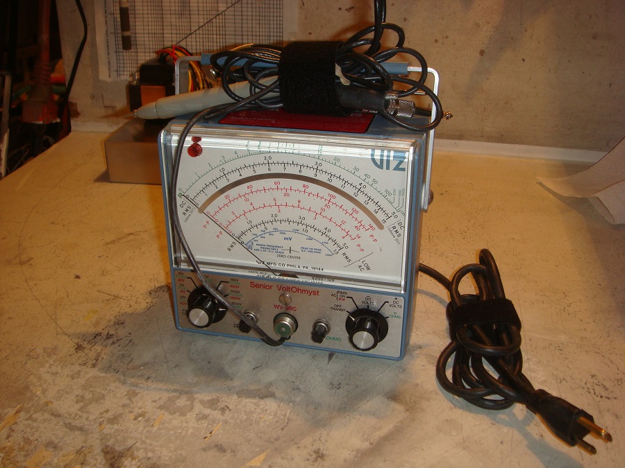
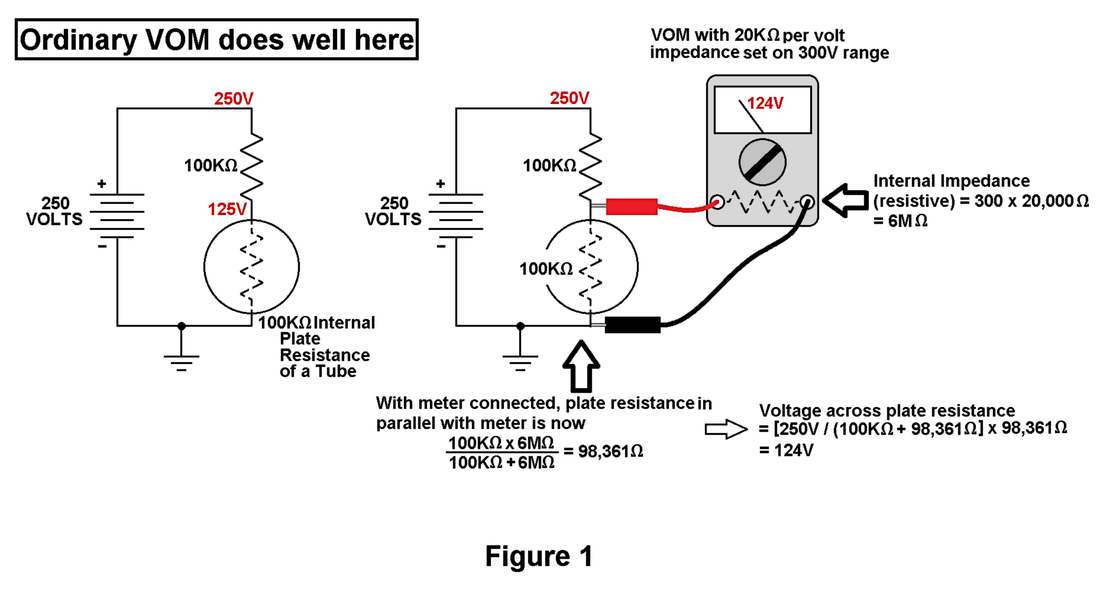
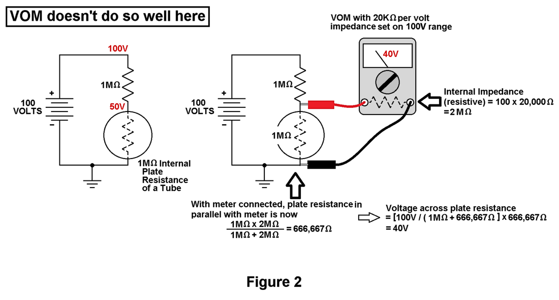
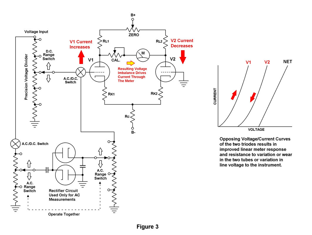
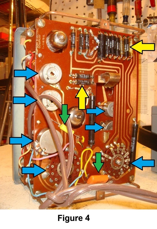
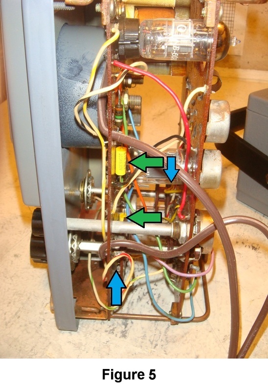
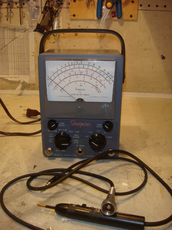
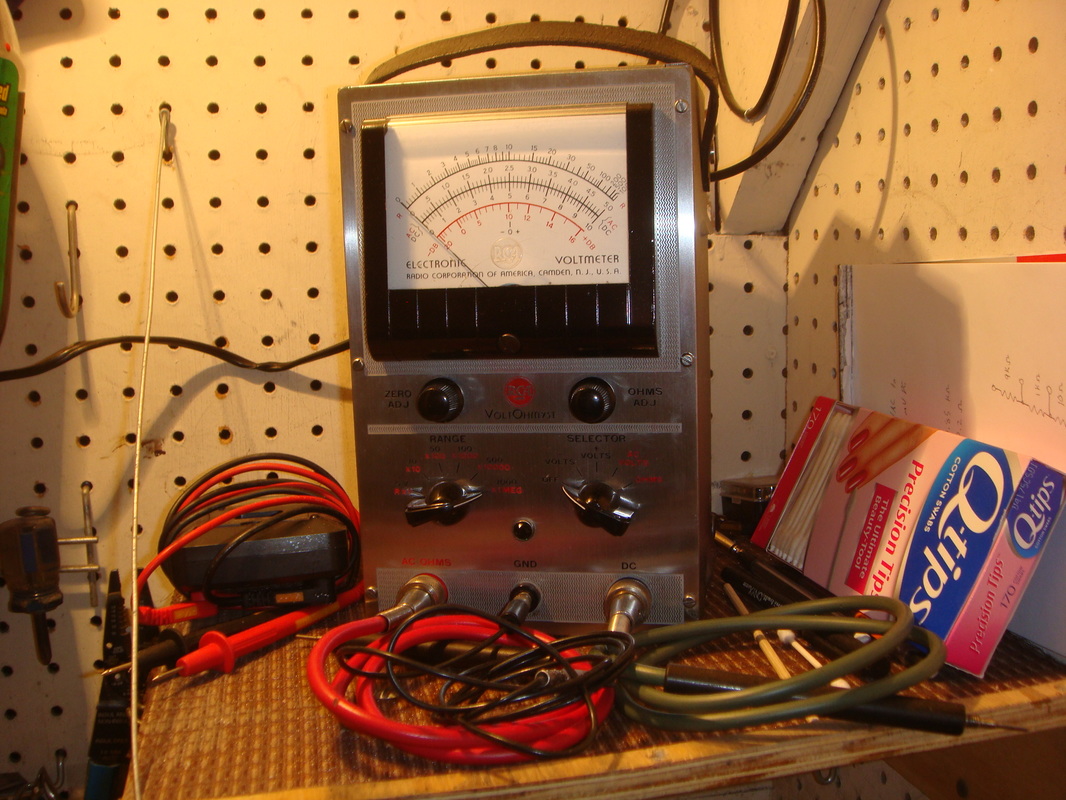
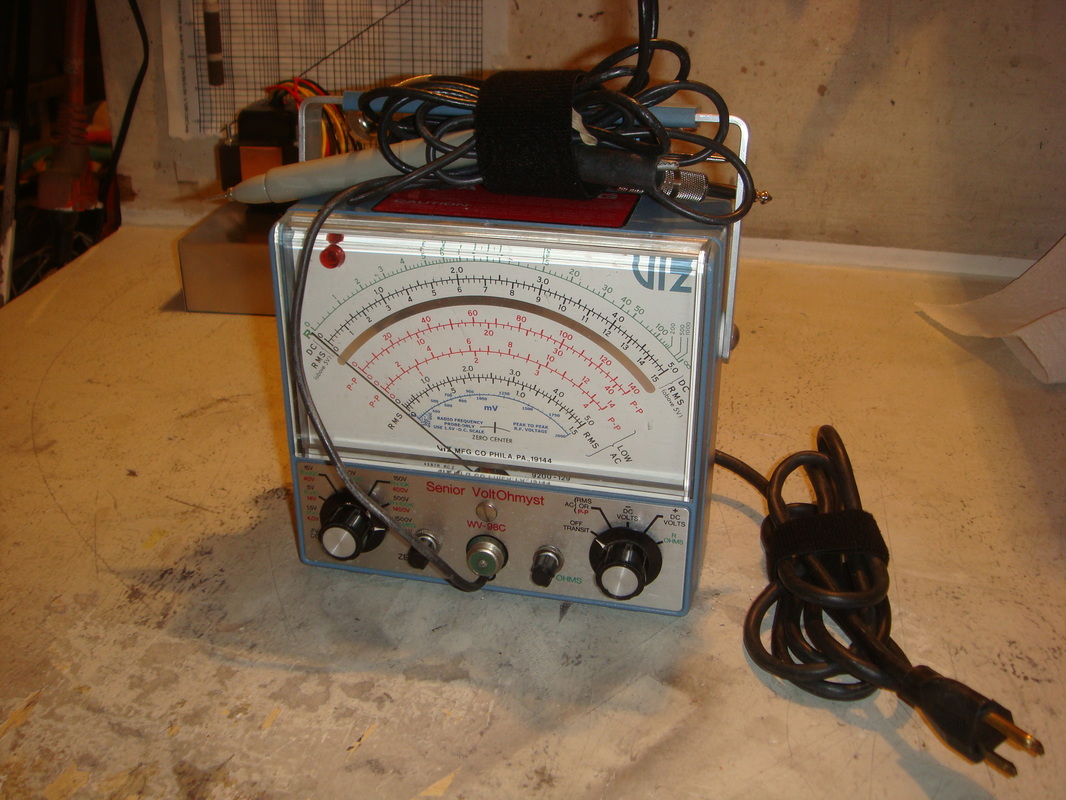
Vacuum Tube Voltmeters Disclaimer The content of this website and blog has been created and posted here solely for the purposes of reading interest by Rob's Radio-Active, LLC. The content is the thoughts of the author and is not intended to be an authoritative guide. There may be errors and omissions. Electronic and electrical devices pose a potential hazard to life and property if improperly handled, used, or serviced. The author cannot possibly think of, and warn of, all the ways one can get into trouble with electricity, and recommends one learn all of the technical and safety aspects of electrical/electronics before attempting to work with or use any of it. There are hazardous voltages and currents involved in almost all electrical and electronic equipment—especially vacuum tube devices or anything that plugs into mains current for operation. Furthermore, vintage equipment was never designed or built to be up the safety standards of modern times. Introduction As a young man back in the early '80s, I was enrolled in one of the local community college's electronics vocational programs. The only piece of test equipment that we were required to buy was a VOM (an analog Volt-Ohm-Milliammeter). The rest of the equipment was provided for classroom use by the college. Our work areas each had a bench top type digital multimeter, DC power supply, Simpson 260 VOM, an oscilloscope, and a few other odds and ends. By that time in electronics history we were primarily learning about solid state television, radio/stereo, and industrial electronics—although there were a few instructors who still used vacuum tubes circuits in most of their examples. Naturally, about this time, I became keenly interested in a friend of mine's dad's long abandoned electronics workshop. It was in a separate room attached to the back of their family garage and it still held most of the tools and parts, although now in disarray, that his dad had used back in the 1960s as a sideline business repairing TVs and radios. Many summer days my friend and I spent hours back there digging through boxes of tubes and playing with some of the test equipment when there was nothing else to do. This is where I saw my first vacuum tube voltmeter. I don't remember what kind it was (Though EICO comes to mind), but I remember the ventilated metal case, its hefty weight, and being very puzzled by a large analog meter that you had to plug into the wall and warm-up before using. At the time, I didn't appreciate its importance in an old-time electronics workshop. Vacuum Tube Voltmeters and Impedance Now of course the school taught us about the importance of using a "high impedance" meter—like our digitals—for measuring voltages in high impedance (to current flow) circuits such as vacuum tube or FET circuits. They also taught us that you could often get by with a decent quality VOM by using the highest voltage range on which you could get a readable number. The principle is simply that if one is using a low impedance meter like a VOM (especially on a low voltage range) the meter will pull excessive current from the high impedance circuit. A circuit with high internal impedance may have all sorts of voltage on it, but it can supply little current and maintain that voltage—like trying to drain a gallon of water from a skinny little, high pressure water pipe. If a hypothetically big, water hungry pressure gauge tried to measure the pressure (equivalent to voltage), the pipe couldn't supply very much water (equivalent to current) and the pressure you read would be incorrectly low. When the gauge was removed, the pressure would jump back up, but you would never see that. It works much the same way with voltages and circuit loading by a meter such as a VOM. (See Figures 1 and 2) There are workarounds, sometimes, like using a "bias box" on the return side of the VOM to zero out the meter and make pretty much an infinite impedance device out of it, at least for DC voltage measurements, but it is not "everyday practical" to do that, so I won't get into those details. Well, back in the day the vacuum tube voltmeter, or VTVM, was the best way to get accurate voltage measurements for both AC and DC voltages in high impedance tube circuitry. Later, high impedance digital meters came along and allowed for this, too, but with more features and great precision. Advantages So why write about or use VTVMs? Well, I won't be one of those who tells you that they are indispensible equipment for working on vintage tube electronics with their characteristic high voltages and internal impedances to current flow. There is a huge market for test equipment of all sorts out there. There are a lot of folks who work with both vintage and new vacuum tube or high impedance FET circuitry, and yet no one on earth that I am aware of makes VTVMs or solid state equivalents for a high impedance, analog movement, general purpose test meter. Someone would make them if they were truly essential. In fact, you should be able to get by just fine with a good digital meter (preferably one with a moving bar graph feature for seeing rapidly changing events, like my Triplett 9045) along with a good, analog (read: 20,000 ohms per volt impedance on DC and at least 5,000 on AC) VOM. Does this mean that VTVMs are just a novelty? Far from it. They have their advantages and are very nice to have. I am only saying do not fret that you cannot diagnose vintage tube electronics or tube amplifiers without one. How you use any kind of meter is at least as important as what kind of meter(s) you use. Admittedly, I like using them, in part, because they're cool. Using vintage test equipment on vintage electronics is highly satisfying to me. But in a practical sense, an analog meter movement with is swinging needle is faster and easier to read than numbers changing or even a digital bar graph when voltages or resistances are changing, such as when "peaking" an adjustment or looking for discontinuity on a potentiometer. An ordinary VOM can do this, too, but lacks the high input impedance (and usually the high frequency response for AC) that a VTVM has. A concentrating eye and a steady hand can certainly learn to make good use of a digital meter or VOM under these conditions, but I still recommend a VTVM as a purchase not regretted. VTVMs are still widely available on eBay and ham fests, but plan on a thorough checkout and restoration job. Fortunately, most of these are not terribly complicated and if the meter movement itself is OK and it's not corroded internally, it is usually a matter of clean-up, replacing a few capacitors, and checking resistor values. The tubes are run lightly in VTVMs and are seldom bad. What else can a VTVM do well? In addition to being able to read AC or DC voltages in high impedance circuits without substantially loading those voltages down, and having the analog meter for easy reading of changing voltages, they usually have a much higher frequency bandwidth for reading AC voltages accurately. This is particularly important when measuring voltage gain of a signal passing through an audio amplifier. A typical digital meter may only be specified to its maximum accuracy at up to 400Hz or so. In my experience, most work fine up to 1kHz or maybe 2kHz, but the voltage reading falls off rapidly above those frequencies—which doesn't help much when trying to measure audio gain and frequency response of an audio amplifier from, say, 20Hz to 20kHz. An ordinary VOM will usually do much better than the digital here, but the frequency response of VOMs is not normally given in the manual as it is with a VTVM—leading to further testing or guesswork— and it also will load down many circuits as it did with the DC voltage examples. This is an important use for VTVMs in my opinion. In a pinch, and if you know what you are doing, a digital meter can be rigged up with a rectifying diode/capacitor adapter on the "hot" test lead to convert a wide frequency range to DC, and the meter will read it as a DC proportional to the peak AC voltage, but this method also requires calibrating or cross checking the probe adapter's output against a known AC voltage within the meter's normal frequency range to account for diode voltage losses (which varies with voltage) to get truly accurate readings. Lacking a VTVM and working on high impedance circuitry, most people just use an oscilloscope for this sort of thing rather than messing with all of that. (Fortunately, new and used "scopes" are available for not too much money these days.) VTVMs really shine where a wide range of frequencies are involved. Resistance and burn out resistance— A couple of last things that I find of particular merit: Most digital meters read resistance up to 40 megohms or so, which is pretty good, but VTVMs will read up to a billion(!) ohms. VOMs typically can read only up to one or maybe a few megohms with any accuracy. Sometimes when checking for leakage currents, this high VTVM resistance range comes in quite handy. Burn out resistance simply means that VTVMs are inherently rugged in regard to hookup mistakes. A VOM or a (especially a cheap) digital meter can be destroyed by having the meter's settings adjusted incorrectly for what is to be measured. The current through the VTVM's meter movement is limited by the current carrying capacity of the vacuum tubes that drive it, and they are difficult to burn out. Also, a typical digital meter's upper voltage limit is most often around 600V. A very carefully constructed resistive voltage divider that does not exceed the voltage ratings of the individual resistors can be used to measure higher voltages, if you really know what you are doing, but the VTVM normally comes with a 1000V or 1200V rating. There are some tube electronics where the B+ voltage to the tubes approaches or exceeds 600V. There are the most important pros and cons of the three main types of meters as I see it. As I have indicated, there are various workarounds to make the different meters give you the circuit information that you need...and by the way, if you are doing a much electronics work, and don't already own one, I do recommend getting an oscilloscope, too, when you can...but though I find that I use a digital (DMM) for quick everyday checks, and sometimes a VOM, too, my VTVM always sits on the shelf above my bench, plugged in and warmed up, when I am working on almost anything in the shop. So how does it work? A simplified description: Most service type VTVMs use a similar circuit whereby a pair of triode tubes (or more commonly, dual triode sections within the same tube envelope) to amplify the DC voltage coming in through the probe and range voltage divider to drive the meter. There is one "active tube" and one "inactive tube" (or more properly, "reactive tube"). These work together in opposing fashion to drive the meter, and this also isolates the meter's current drain from the circuit being measured. The voltage to be measure is first applied through the probe cable to the "top" of a precision resistor voltage divider with a typical resistance of ten megohms on all ranges. The range switch connects the active tube's grid to points along the resistive divider chain. The higher the voltage to be measured, the "lower" the connection point will be on the divider since, by design, it always takes a set amount of voltage on the tube grid to drive the meter to full deflection. (See Figure 3) The triode tubes are arranged in what is called a "balanced bridge" circuit. (Figure 3 again) A positive voltage, for example, coming to V1, the active tube's grid causes the tube to increase its current conduction. This causes an increased voltage drop across the resistors RL1, RK1, and RC, so that the plate voltage becomes less positive (more negative), and the cathode becomes more positive (less negative). RC is made to be of a considerably higher resistance than RK1 or RK2, so most of the positive voltage increase in the cathode circuit occurs across RC. Since the cathode of V2 is also connected through its cathode resistor to RC, V2 cathode also becomes more positive—almost as much as V1's cathode. V2's grid is grounded and its voltage is therefore fixed at zero volts. The effect of V2's cathode becoming more positive relative to its grid is the same as if its grid were driven more negative, and its V2's current decreases. So to recap, V1 current increases and causes V2 current to decrease about the same amount. This causes the plate voltages to move in opposite directions. The meter is connected, through the calibration potentiometer, between the two tube plate circuits, and a proportional current is driven through it to cause a proportional needle deflection. The zero potentiometer allows for balancing the tube currents to be exactly the same with no measurement voltage applied so that the meter needle rests on zero. Since the same voltage divider and all other components are the same for all voltage ranges, and because of this it takes a certain set amount of voltage on the V1's grid to cause a given amount of meter deflection, setting the meter calibration on one voltage range (whatever is stated in the manual) will calibrate the meter for all ranges. This assumes, of course, that all the resistor values in the input voltage divider are correct and therefore properly proportional to each other. The advantage of the bridge circuit is that as V1 current increases through its inherently non-linear voltage/current curve, V2 is going the other way on its curve. The net result is that the response of the meter is much more linear than if only one triode were used to amplify the input voltage. It also compensates, to a large degree, the effects of the two triodes having different characteristic curves due to manufacturing tolerances, or tube aging. Additionally, it compensates for variation in line voltage to the instrument since both tubes react the same way to an increase or decrease in power supply voltage. This saves expense and complication of a regulated power supply for ordinary service grade VTVMs—although most laboratory grade VTVMs do use a regulated supply to enhance accuracy even further. If AC is to be measured, the incoming AC voltage is sent through a rectifier circuit with its own range voltage dividers —one to prevent overvoltage from reaching the rectifier tube, and another at the rectifier tube output to scale the voltage to the correct level. This converts the AC to DC, where it acts the same way as a DC measurement voltage on the bridge tube circuit. This is why there is also a rectifier tube in a VTVM, even if it uses a solid state diode or selenium rectifier for the power supply. The resistance measuring function uses all the same circuitry as the voltage measurement functions, but supplies current from a battery (1.5 to 3V) through another set of internal precision resistors used only for the ohms function, and out through the resistance to be measured. The voltage drop across the ohms function resistor being used divides with the unknown resistance, and this voltage is applied to the grid of V1 to operate the meter drive circuit as before. A battery provides a fairly stable DC voltage for the ohms operation since its voltage is set by its chemical composition for a given current drain. The drain is very, very small on the battery and it tends to last and maintain an accurate voltage for a very long time. The only downside of that is that the battery tends to be forgotten, and especially when the VTVM is put away into storage with an old and substantially drained battery, they can leak corrosive chemicals inside the meter and do a lot of damage. This is one of the most common headaches in trying to restore a VTVM to working condition. Restoration When a new-old VTVM comes across my bench, the first thing I do is put a 1.5V battery in series with a 10K ohm potentiometer and hook up one side of the potentiometer to the meter and the loose battery end to the other side of the meter. This allows me to run the voltage up and down to get an idea if the meter movement is working and not sticking. Make sure the polarity is correct so that the meter moves the right way. If the meter passes this test, I deem it worth taking a chance on restoring the rest of the unit. In general, I clean it up and check that all the screws and nuts are tight because they are often used for ground returns, and dirty or corroded contacts there can cause all sorts of headaches. I use rubbing alcohol for general dirt and grime removal, along with a spray of electrical contact cleaner—but keep these away from any plastic parts or painted surfaces until you know they will not damage them. Do not use WD-40 or similar products to clean or lubricate the switches—especially the rotary switches that select the function and range of the meter. Products like this can cause small current leakage paths that will make the meter operate erratically, and it is difficult, at best, to remove. I clean all of the potentiometers and switches (Figures 3 and 4, blue arrows) with Caig De-Oxit and work them back and forth several times. Wipe up excess fluid. I replace any paper/wax capacitors, any electrolytic capacitors, (Figures 4 and 5, green arrows) and any resistors that measure out of tolerance. Especially be particular about the one percent tolerance resistors used in the input voltage divider circuit. (Figures 4 and 5, yellow arrows)These resistors are usually mounted on the rotary range switch, but in this case they are lined up on the main circuit board. If any of these are out of tolerance, the voltages the meter reads will be off. It could be calibrated to read correctly on one voltage range, but then it would be off on other ranges. They all work together in a series string. These precision divider resistors are usually odd values that sometimes may be special ordered, or more conveniently, made up of series/parallel combinations of one percent tolerance metal film resistors. It is important to have the owners/service manual for your VTVM so that you can then calibrate it correctly. There is a definite order in which calibration adjustments must be made, and your manual will have all of that information in a step by step format. Paper manuals can be purchased on eBay, or from ManualMan.com online if you can't find a free download. I usually look at The Boat Anchor Manual Archive and get them there for free. Heathkit manuals usually must be purchased due to some confusing copyright issue, where someone apparently bought the rights to all of their equipment manuals. A word about the probes used for VTVMs: If you decide to buy and checkout/fix-up and use a VTVM, try to get one with the original probes. They do use special probes with shielded cable, an isolation resistor in the probe handle, and very often they use those sometimes-hard-to-find, obsolete microphone connectors. The connectors can be changed on the VTVM to fit readily available BNC connectors, but you would still need to fabricate a probe with an isolation resistor in the probing end for use with DC measurements, another probe without the resistor for AC measurements, and make sure they could safely handle the high voltages that the VTVM is capable of reading. Typically, the factory probe has a switch in the handle for "AC/Ohms" and "DC." On DC mode, the resistor is switched in line with the cable—usually a 1 megohm resistor. This resistor is there to decouple the shielded cable's own capacitance from the circuit being measured to prevent excessively disturbing the circuit operation. Oscillators in radio receivers would stop functioning without it, and that would ruin the DC voltage they generate as a tube grid bias. The resistor needs to be there in the probe tip for DC, and not be there for AC or ohms measurements. The meter will not calibrate correctly without the probe with its isolation resistor, so don't forget to switch the switch during meter calibration or everyday use. It is also a good idea to check that resistor's ohms value when fixing up a VTVM. It is easy to overlook that, and they often drift in value with age. I hope you enjoyed reading! © 2016 Rob's Radio-Active, LLC All Rights Reserved Some of my VTVMs
2 Comments
|

 RSS Feed
