|
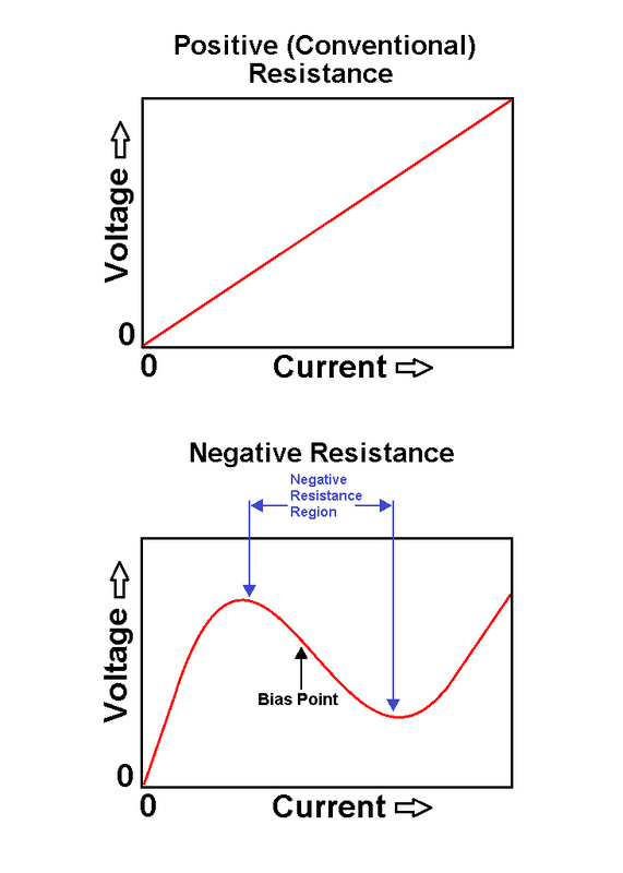
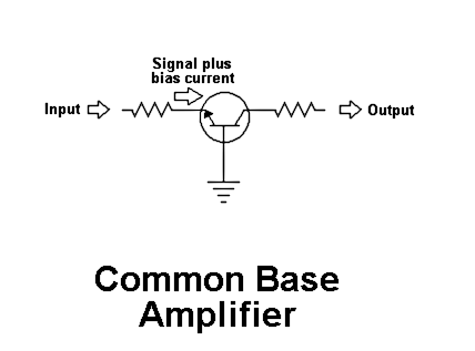
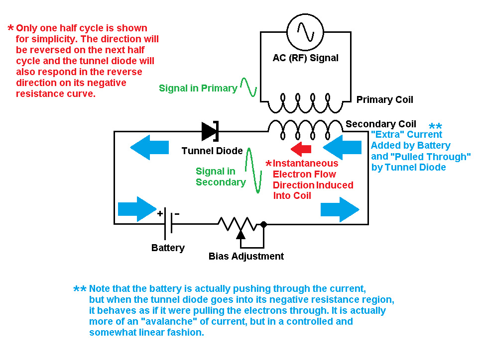
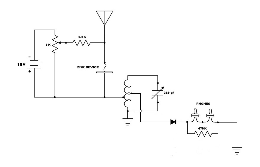
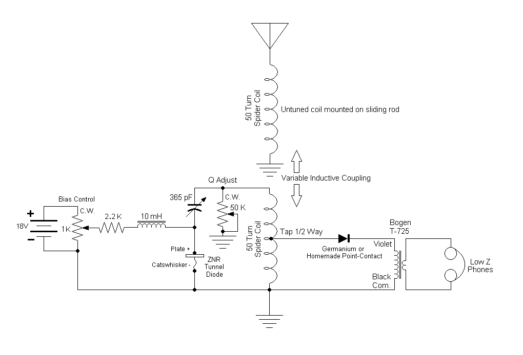
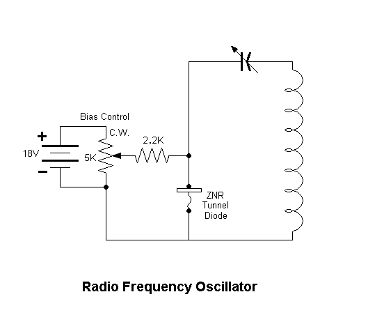
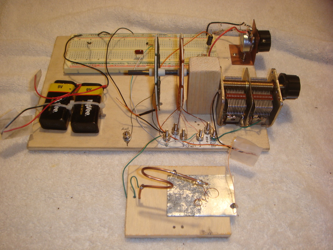
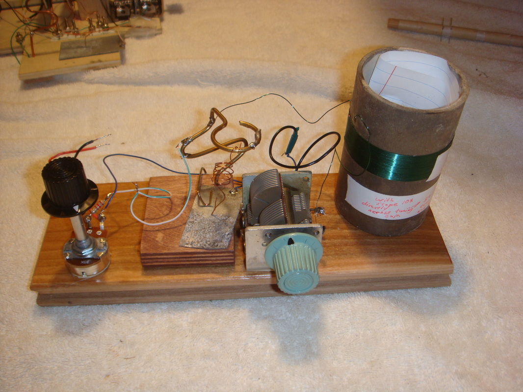
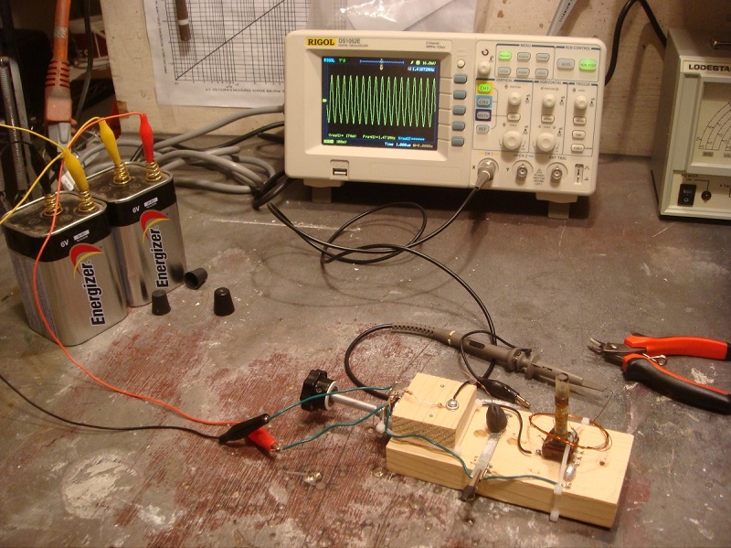
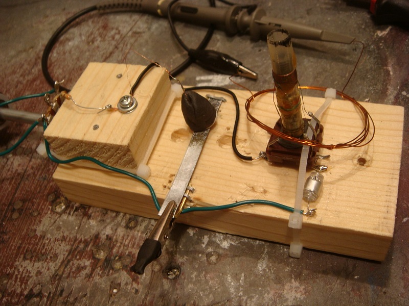
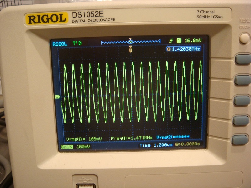
I learned to make my own point contact tunnel diodes from zinc oxide from Nyle Steiner's website, sparkbangbuzz.com. There are other materials that can work, too, but I haven't tried them. I found it almost unbelievable that a person could make a solid state device capable of amplification at home so easily so I had to try it. It worked. It took some effort on my part—but it worked. It worked a number of times with as many as I made. I knew that a number of dissimilar metals or metal oxides in light contact with a copper or steel wire point (at the right place found by experimentation) would make a small signal rectifier (detector) suitable for an all-homemade crystal radio receiver and I had done some of those. This one is different. It has a property known as differential negative resistance, which means it can actually amplify a radio signal. This one is a homemade tunnel diode. (It also makes a lousy crystal radio detector, so use it in conjunction with another homemade or store-bought detector diode.) So what is a tunnel diode? It conducts electricity more easily in one direction than the other like most diodes do, but in its forward biased condition, there reaches a point where DC current applied to it with a battery sort of "avalanches" through it in such a way as to exhibit the opposite of resistance to current flow—negative resistance. This causes the voltage across it to drop as the current increases. (See illustration 1.) And here is a more technical description of negative resistance and amplification. Illustration 1 The voltage applied to the entire circuit remains the same, so this excess voltage appears across, as well as the increase in current through, a load in series with the tunnel diode. Since this happens more or less linearly, it reproduces the inputted signal as an increase in voltage and current in the load...Almost like a transistor with its controlling base (or gate) being a part of the main current path with the collector (or drain) and emitter (or source) somewhat like a common base amplifier using a transistor. The gain parameters between the two are very different though, with the tunnel diode circuit giving more actual power gain. (See Common Base Amplifier and illustration 2 below.) Illustration 2 I have used this homemade version to make radio frequency oscillators (up to 10 MHz or so) and to amplify the radio signal in a crystal radio receiver before the detector. Used this way it can make a very loud and sensitive crystal radio—all with homemade parts. The best results I obtained were with a regenerative type receiver built for the AM broadcast band. Hooked to my outdoor CB base station antenna, I have been able to hear 5kW station in the daytime more than 70 miles away that sounded like they were less than a mile. Very loud and clear. In case you are not familiar, a regenerative receiver is one designed to have intentional and adjustable positive feedback. Not enough to oscillate freely into a squeal, but set just below that threshold so that any incoming radio signal gets re-amplified by the same circuit. I will not go into more detail here, but they are quite sensitive. The homemade tunnel diode can also work very well in a straight, conventional crystal radio receiver without regeneration—and I have included schematics for both types. (See illustrations 3 for basic, 4 for a regen., and 5 for an oscillator.) Illustration 3 Illustration 4 Illustration 5 In case you are wondering, these do not seem to work well (or at all) for audio amplification for some reason, though it may be possible. They amplify the radio signal and then it is detected into a stronger audio signal by another more conventional diode—homemade or factory made. You still need earphones, but I have measured a power gain of up to 20dB or so. The homemade tunnel diode (which I refer to as ZNR for "zinc negative resistance" device) is easily made from galvanized steel like used in air ductwork for furnaces and air conditioners. A piece, perhaps 2 inches (~60cm) by 2 inches is held in some vice grips or pliers and part of the underside is heated with a propane torch. (This produces noxious fumes and flying sparks, so do it outside and upwind with gloves and safety goggles.) When the metal gets hot enough, white sparks pop away from the topside quite vigorously. After it is sparking really well, the metal is allowed to cool. I have had the best luck with letting it cool for 10 seconds or so, and plunging it into clean (and preferably distilled) water. This cleans off the yellowish oxide formations and leaves a piece of metal looking dull-whitish and speckled with little dark spots. The still "un-cooked" part of the sheet metal from under the pliers is used for clipping on the positive side the electrical connection. A small copper wire like solid 22 or 24AWG is the negative connection, and it is placed in light contact with the sheet metal's spotty upper side. How light? I found perhaps half a gram to two grams, just to give you an idea. The best places to try for tunnel diode action are usually on or at the edges of the little dark spots. Sometimes the copper wire is better cut off square at the contact end and sometimes it works better to bend the end sharply back on itself to create a small rounded contact end. Some pieces will have many, many working spots and others not. Also, some spots or contact pressure work better than others both in amplification and in audible clarity of the radio signal. The first time you do this will take a lot of patience, but with a little experience you can listen to the earphone for rushing or squealing noises to indicate a possible "live" spot, and adjust the bias potentiometer for reception rather quickly. You will usually also have to retune the receiver a bit when you start getting something. When it's working, it tends to detune it somewhat, and sometimes quite a lot. I like to start the bias pot at a little more than halfway to the highest voltage output (say, 10 volts) and do the contact probing next. Pictures below are of a couple of devices that I made that work very well. The first is a regenerative receiver the second is an RF oscillator that can be picked up on an AM radio for a considerable distance away. I made no attempt to make them pretty or particularly portable. An old forum posting here at The EEVblog Forum, by myself "Mr. Coffee" has a bit more detail if you are interested. Below are a few more pictures of my very first RF oscillator to prove to myself that there was amplification. No amplification makes sustained oscillation of the resonant circuit impossible, of course. The voltage on the scope shows 168 millivolts (RMS) but it was actually several volts in the oscillator circuit itself. The lower scope reading was because it was loosely coupled to the oscillator with just a little coil in proximity to the oscillator's coil.
If you don't want to mess with making this device and fooling around with finding active spots, etc., but want to experiment with the concept of negative resistance, a cheap 2N2222 transistor from Radio Shack can be used instead. See here for a great webpage on doing just that. Have fun and be careful. © 2016 Rob's Radio-Active, LLC All Rights Reserved
3 Comments
Bill Allsopp W 5 TJ I
7/4/2018 09:30:19 pm
After about ten years of other projects, I have come back to having thoughts on negative resistance and how it can be used in radio tinkering.
Reply
Leave a Reply. |
AuthorRob Tracy is the operator of Rob's Radio-Active, LLC. Parts and vintage stereo, radio, audio, and test equipment sales and restoration services. |
